고급컴퓨터그래픽스 4. Image Processing
건국대학교 고급컴퓨터그래픽스 김형석 교수님의 수업을 정리한 내용입니다.
Image Processing
Computer Graphics는, 정보를 통해 이미지를 만들어내는 과정이다. Computer Vision는, 반대로 이미지를 통해 의미있는 정보를 추출하는 과정이다. Image Processing는, 이미지를 인풋으로 넣어 아웃풋 이미지를 얻어낸다.
사진 보정, Game Post Processing 등이 대표적인 Image Processing 이다.
Post Processing은 어떻게 구현되는가가
Pipeline을 거쳐 생성한 이미지를, 다시 쉐이더로 어떻게 보낼 수 있을까?
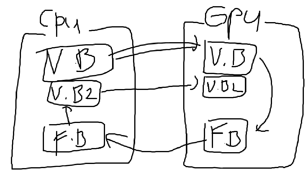
[!error] 이미지를 다시 픽셀 단위로 쪼개서 데이터로 보내면 되려나?{title}
그렇게 하면 위와 같은 그림이 될텐데, CPU <-> GPU로 넘어가는 연산이 무지 느리기 떄문에, 넘어가는 연산을 최대한 줄여야 한다. 따라서 바람직한 방법은 아니다.
[!success] Frame Buffer 에 있는걸 바로 CPU로 아웃풋 하지말고 후처리까지 끝내서 보내면 되지 않을까? {title}
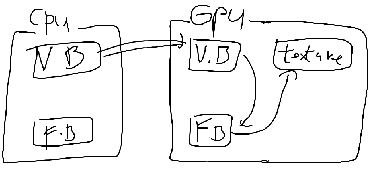
GPU에 있는 Frame Buffer 정보를 이용해서 Texture Imgage를 GPU 내에서 생성한다. 이 Texture와 같은 것을 Frame Buffer Obejct라고 부른다.
이런식으로 여러 번의 Randering 과정을 거치는 것을 Multi-pass Rendering 기법이라 부른다.
Image Processing 전용 Shader 만드는 방법
Fragment Shader에서 대부분의 과정을 처리하고,
Texture, Texture Coords (텍스쳐 좌표)를 Input으로 받아야 한다.
- Input으로 Texture Coords 넘기는 방식
1
2
3
4
5
6
7
8
9
10
11
12
13
14
15
16
17
18
19
20
21
// Vertex Shader
in vec3 Position;
in vec2 TextureCoord;
out vec2 fs_TextureCoord;

void main(void)
{
    fs_TextureCoord = TextureCoord;
    gl_Position = vec4(Position, 1.0);
}

// Fragment Shader
uniform sampler2D u_Image;

in vec2 fs_TextureCoord;
out vec4 out_Color;

void main(void)
{
    out_Color = texture(u_Image, fs_TextureCoord);
}
[!question] What is Texture Coords (텍스쳐 좌표)?{title} UV Coordinate를 사용하며, 이 정점이 Texture Image가 (0,0) ~ (1,1) 크기일 때 어느 Texture Point를 참조하는지 나타낸다.
- 직접 계산하는 방식
1
2
3
4
5
6
7
8
9
10
11
12
13
14
15
16
17
18
19
20
// Vertex Shader
in vec3 Position;

void main(void)
{
    gl_Position = vec4(Position, 1.0);
}

// Fragment Shader
uniform sampler2D u_Image;
uniform vec2 u_inverseViewportDimensions;

out vec4 out_Color;

void main(void)
{
    vec2 txCoord = u_inverseViewportDimensions * gl_FragCoord.xy;

    out_Color = texture(u_Image, txCoord);
}
[!question] What is u_inverseViewportDimensions, gl_FragCoord?{title} u_inverseViewportDimensions: 해상도의 역수 벡터. 예를들어, \(1920 \times 1080\) 해상도면 이 벡터의 값은 \(\left( \frac{1}{1920}, \frac{1}{1080} \right)\)이 되겠다.
gl_FragCoord: 현재 Fragment의 화면 공간 좌표를 제공함. Viewport의 범위를 갖는다. 예를들어, \(1920 \times 1080\) 해상도면 gl_FragCoord는 \((0 \sim 1919, 0 \sim 1079)\) 값을 가질 수 있다.
인접한 Texel을 얻는 방법
Texture의 좌표를 texel (텍셀)이라고 부른다.
Edge Detection나 Toon Rendering 같은 거 구현하려면 텍스쳐의 주변 점까지 봐야하는데, 어떻게 주변 점을 볼 수 있을까?
- 직접 구현
1
2
3
4
5
6
7
8
9
10
11
12
13
14
15
16
17
uniform sampler2D u_Image;

in vec2 fs_TextureCoord;
out vec4 out_Color;

void main(void)
{
    vec2 delta = 1.0 / textureSize(u_Image);

    vec4 c0 = texture(u_Image, fs_TextureCoord);
    vec4 c1 = texture(u_Image, (delta * vec2(-1.0, 0.0)));
    vec4 c2 = texture(u_Image, (delta * vec2( 1.0, 0.0)));
    vec4 c3 = texture(u_Image, (delta * vec2( 0.0, -1.0)));
    vec4 c4 = texture(u_Image, (delta * vec2( 0.0, 1.0)));

    out_Color = (c0 + c1 + c2 + c3 + c4) * 0.2;
}
[!question]- Why?{title} UV Coordinate는 (0,0) ~ (1,1)로 되어있더라도, 실제 텍스쳐 사이즈는 \(1024 \times 512\)일지 \(256 \times 256\)일지 모르는 일이다.
따라서, Texture Size를 통해 다음을 계산하면 된다. 바로 위 아래 텍스쳐 픽셀의 위치
\[\text{uv} \pm \frac{1}{\text{textureWidth}}\]바로 좌우 텍스쳐 픽셀의 위치
\[\text{uv} \pm \frac{1}{\text{textureHeight}}\]
- textureOffset 함수 사용
1
2
3
4
5
6
7
8
9
10
11
12
13
14
15
uniform sampler2D u_Image;

in vec2 fs_TextureCoord;
out vec4 out_Color;

void main(void)
{
    vec4 c0 = texture(u_Image, fs_TextureCoord);
    vec4 c1 = textureOffset(u_Image, fs_TextureCoord, ivec2(-1, 0));
    vec4 c2 = textureOffset(u_Image, fs_TextureCoord, ivec2(1, 0));
    vec4 c3 = textureOffset(u_Image, fs_TextureCoord, ivec2(0, -1));
    vec4 c4 = textureOffset(u_Image, fs_TextureCoord, ivec2(0, 1));

    out_Color = (c0 + c1 + c2 + c3 + c4) * 0.2;
}
프레임 버퍼에 적힌 이미지를 가져오는 함수
처리를 마치면, 이미지 정보가 프레임 버퍼에 남아있고, 이를 가져오는 방법은 다음과 같다.
1
2
3
4
5
6
7
8
9
glUseProgram(/* ... */);
glDraw*(/* ... */);

unsigned char rgb = new unsigned char[width * height * 3];
glReadPixels(0, 0, width, height, GL_RGB, GL_UNSIGNED_BYTE, rgb);

// ...

delete [] rgb;
glReadPixels 함수를 사용하면 정말 느린 Bus 커맨드가 실행되고, 그게 끝날때까지 GPU는 아무것도 안하고 기다린다.
따라서 최소한으로 사용해야 한다.
[!question] 왜 가져오는가?{title} 이미지를 CPU로 가져와서 저장해야 할 때 사용하면 된다.
게임과 같이 가져올 필요 없이 바로 이미지를 출력하면 되는 상황은 필요 없는 함수이다.
Image Processing Example
Negative Color
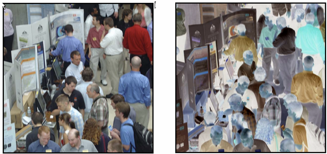
색깔을 반전한다.
1
2
3
4
5
6
7
8
9
10
11
12
13
14
15
16
17
18
19
20
21
22
// Vertex Shader
in vec3 Position;
in vec2 TextureCoord;
out vec2 fs_TextureCoord;

void main(void)
{
    fs_TextureCoord = TextureCoord;
    gl_Position = vec4(Position, 1.0);
}

// Fragment Shader
uniform sampler2D u_Image;

in vec2 fs_TextureCoord;
out vec4 out_Color;

void main(void)
{
    out_Color = texture(u_Image, fs_TextureCoord);
    out_Color.xyz = vec3(1) - color.xyz;
}
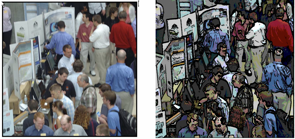
Edge Detection
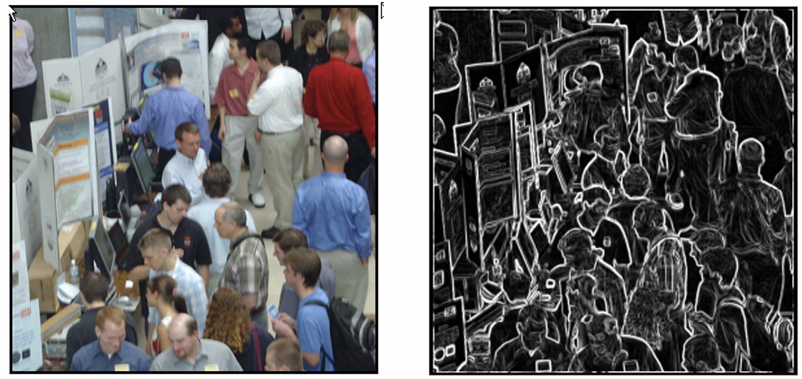
주변 점들과 색깔 차이가 많이 나면 Line을 남기고, 색깔 차이가 적게 나면 색을 없앤다.
Toon Rendering
색 범위가 연속적인 분포로 0 ~ 255 이렇게 있다고 치면,
1~10 범위엔 특정 값 10~20 범위엔 특정 값 …
이런식으로 색깔 분포를 디지털화 하면 카툰 효과를 낼 수 있다.
Average Blur
주변 점의 텍스쳐 색깔을 다 더해서 평균을 낸다.
1
2
3
4
5
6
7
8
9
10
11
12
13
14
15
uniform sampler2D u_Image;

in vec2 fs_TextureCoord;
out vec4 out_Color;

void main(void)
{
    vec4 c0 = texture(u_Image, fs_TextureCoord);
    vec4 c1 = textureOffset(u_Image, fs_TextureCoord, ivec2(-1, 0));
    vec4 c2 = textureOffset(u_Image, fs_TextureCoord, ivec2(1, 0));
    vec4 c3 = textureOffset(u_Image, fs_TextureCoord, ivec2(0, -1));
    vec4 c4 = textureOffset(u_Image, fs_TextureCoord, ivec2(0, 1));

    out_Color = (c0 + c1 + c2 + c3 + c4) * 0.2;
}
Gaussian Blur
\[G(x,y)=\frac{1}{2\pi \sigma^2}e^{ - \frac{{x^2 + y^2}}{2\sigma^2}}\]가우시안 분포를 사용해서 Blur를 만드는 방법이다.
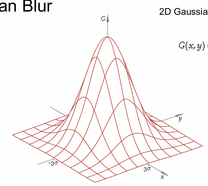
저 식을 사용해서 대충 근사시킨 3x3 행렬은 다음과 같다.
\[\frac{1}{16} \cdot \begin{bmatrix}1&2&1 \\ 2&4&2 \\ 1&2&1 \end{bmatrix}\]1
2
3
4
5
6
7
8
9
10
11
12
13
14
15
16
17
18
19
20
21
22
23
uniform sampler2D u_Image;
in vec2 fs_TextureCoord;
out vec4 out_Color;
void main(void)
{
vec4 up_left = textureOffset(u_Image, fs_TextureCoord, ivec2(-1, 1));
vec4 up_mid = 2 * textureOffset(u_Image, fs_TextureCoord, ivec2(0, 1));
vec4 up_right = textureOffset(u_Image, fs_TextureCoord, ivec2(1, 1));
vec4 left = 2 * textureOffset(u_Image, fs_TextureCoord, ivec2(-1, 0));
vec4 mid = 4 * texture(u_Image, fs_TextureCoord);
vec4 right = 2 * textureOffset(u_Image, fs_TextureCoord, ivec2(1, 0));
vec4 down_left = textureOffset(u_Image, fs_TextureCoord, ivec2(-1, -1));
vec4 down_mid = 2 * textureOffset(u_Image, fs_TextureCoord, ivec2(0, -1));
vec4 down_right = textureOffset(u_Image, fs_TextureCoord, ivec2(1, -1));
out_Color = (up_left + up_mid + up_right +
left + mid + right +
down_left + down_mid + down_right) * 0.0625;
}
[!tip] UV Coordinate의 (0,0)은 왼쪽 아래에서 위, 오른쪽으로 갈수록 값이 증가한다.{title}
Image Processing Operations
Image Processing에서 유용하게 활용할 수 있는 알고리즘들을 소개한다.
사용 가능한 알고리즘의 조건
- Data-parallel 해야 한다.
[!question] What is Data-parallel?{title} 주변 픽셀의 계산 결과에 의존하면 사용하기 힘든 알고리즘이다.
주변 픽셀 계산 결과를 기다리는 동안 다른 모든 쉐이더가 그 계산을 위해 잠시 저장하고, 이게 중첩되면 기하급수적으로 느려져 버린다.
각 픽셀마다 계산 결과가 딱 나와야 Data-parallel하다고 한다.
- Bus를 사용하지 않는 알고리즘
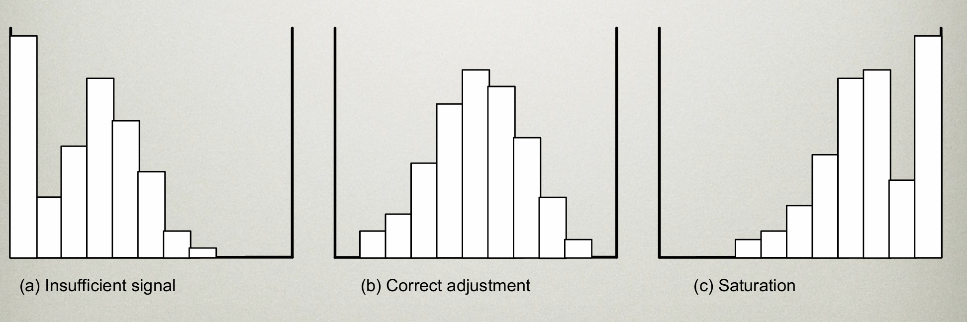
The Grey level histogram
흑백 이미지라고 생각하고, 색깔별로 0인 값, 1인 값, … , 255인 값을 모아 만든 Histogram이다.
[!question]- 왜 필요한가?{title}
- 우리 색깔이 잘 분포되어 있는지 알 수 있다.
셋 중에서, 가장 좋은 분포는 B이다. A는 너무 어둡고, C는 너무 밝다.
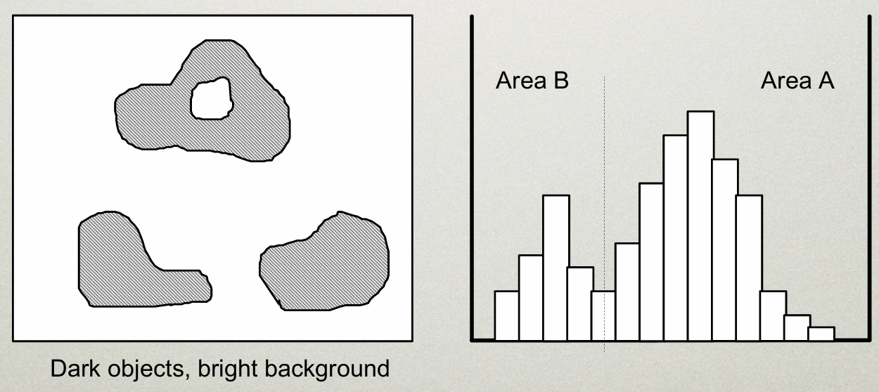
- 영역을 구분할 수 있다.
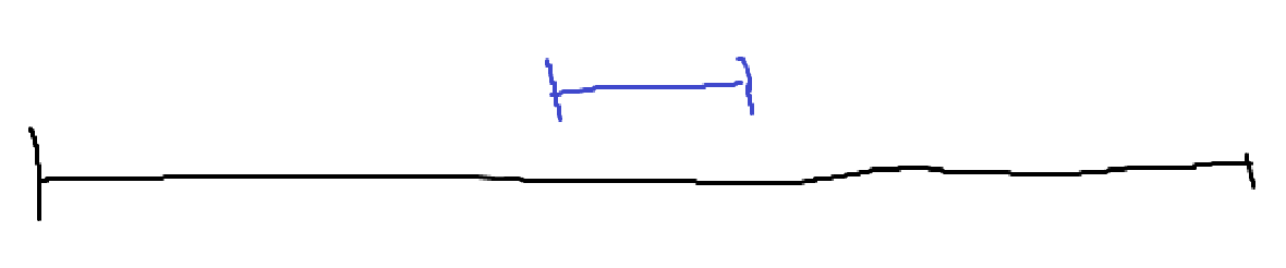
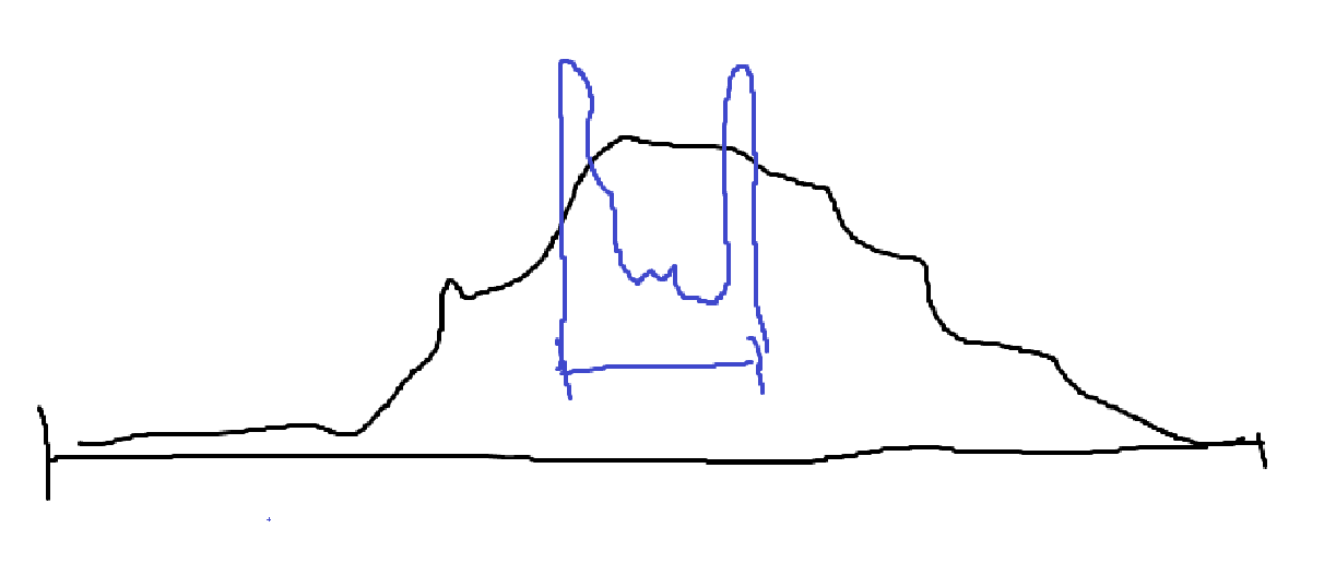
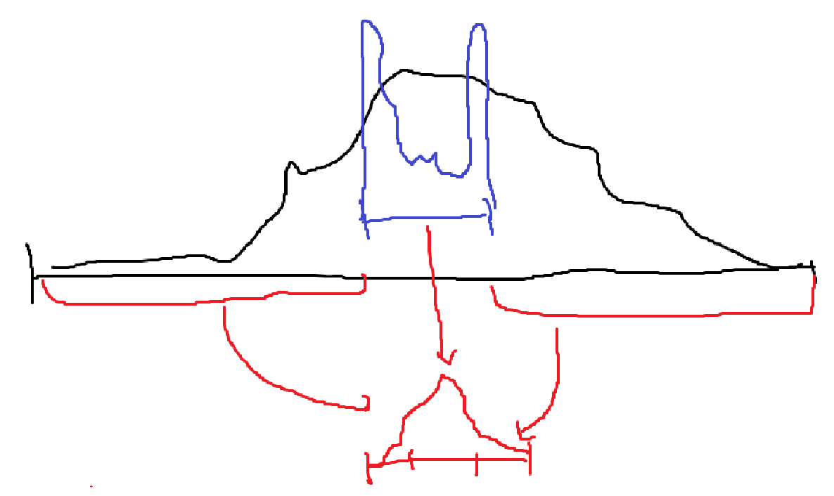
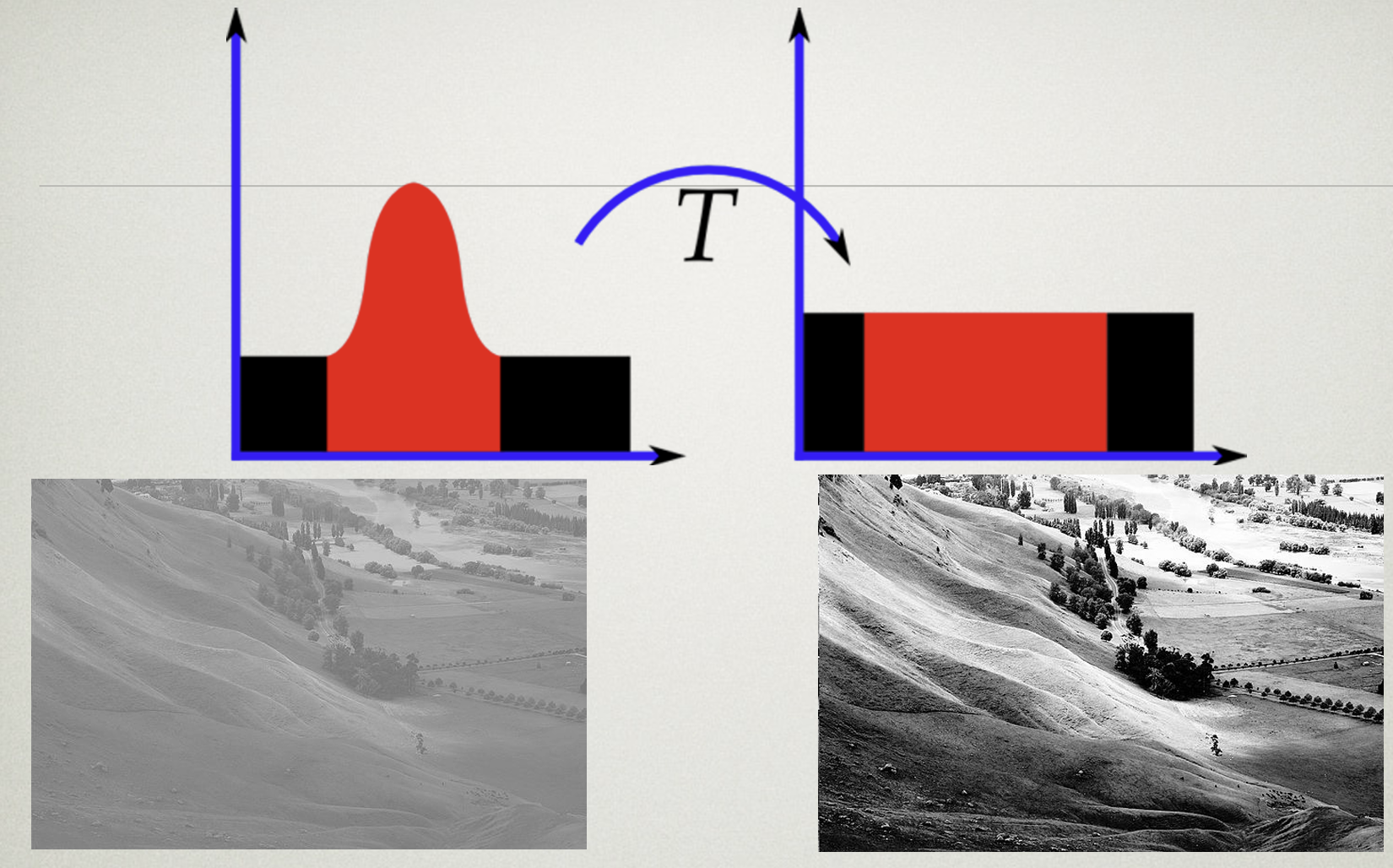
[!example]- HDR Image : High Dynamic Ragne Image{title}
우리 눈이 볼 수 있는 범위가 검은색이면, 컴퓨터가 표현하는 색은 파란색 범위밖에 되지 않는다.
실제 색깔 분포를 옮기면 양쪽 끝에 색깔이 몰려있게 되는데, 이걸 균형있게 옮기는 기술이 HDR이다.
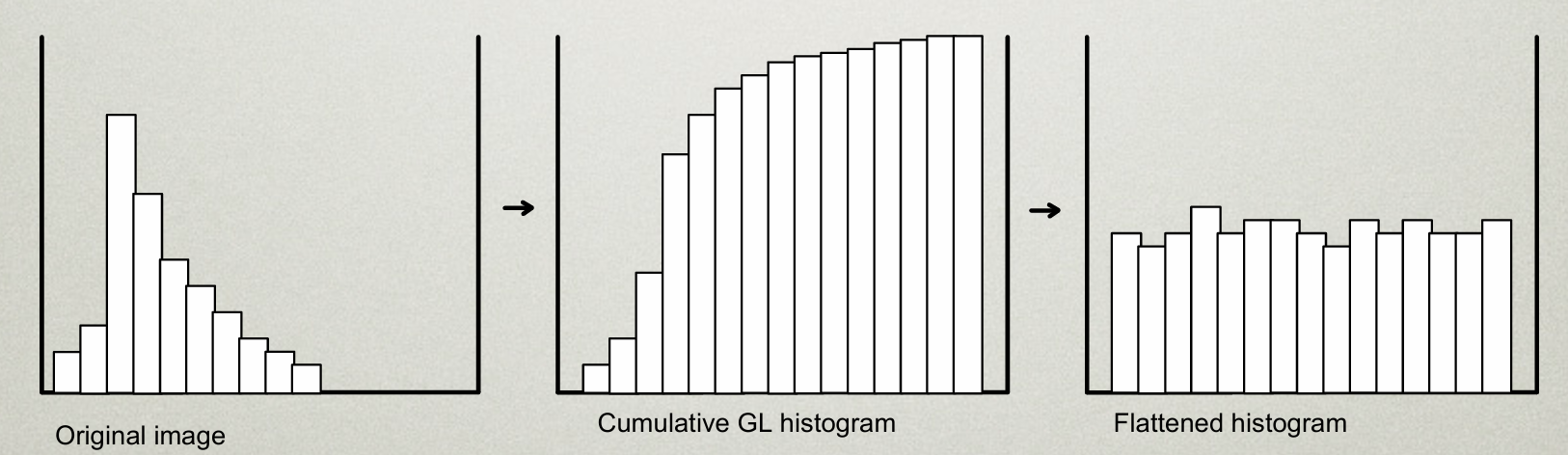
[!example]- Histogram Equalization{title}
한쪽으로 치우친 분포의 Histogram을 평탄하게 만들면, 색깔이 좀더 풍부해지는 효과가 있다.
이걸 쉐이더에서 바로 구현하기는 힘들다.
한번에 작업하려면, 각 픽셀마다 Histogram을 만들고, 그 분포를 보고 색상을 좀 조절하는 연산을 해야하는데
굳이 각 픽셀마다 Histogram을 계산하지 않아도 되기 때문이다.
먼저, 최초 한번 Histogram을 만들고, 다음 과정에서 Histogram을 각 픽셀마다 넣어주면 된다.
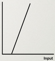
Point operations
각 점의 Color 값을 일관적으로 변환하는 연산자다.
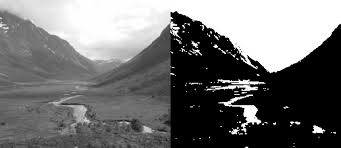
- Threshold
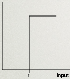
픽셀의 Color 값이 t 이상이면 1, 아니면 0. 특정 범위 이상의 색만 추출한다.
[!example]- Example Code{title}
- Window Threshold
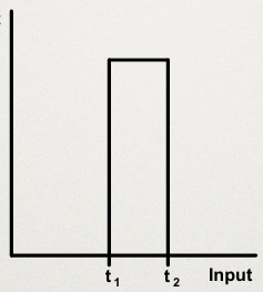
픽셀의 Color 값이 \(t_{1} < t < t_{2}\) 사이면 1, 아니면 0. 특정 영역만 뽑아낼 수 있다.
[!example]- Example Code{title}
- Contrast
어두운 부분을 없애고, 밝은 부분을 취한다.
[!example]- Example Code{title}
- Contrast compression
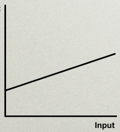
어두운 부분을 적당히 없앤다.
[!example]- Example Code{title}
- Combination
가운데는 흐릿하게, 어둡고 밝은 부분은 확 변하게.
[!example]- Example Code{title}
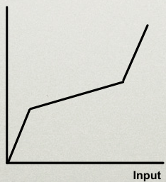
- Contouring
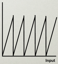
계단식의 밝기를 준다?
[!example]- Example Code{title}
곱하기 = mask할 떄 사용 중간부분만 원형으로 있는 mask를 곱하면 중간부분만 남긴 이미지 만들기 가능
노이즈 절감?
평균 블러 방법
Algebraic operations
두개의 이미지를 연산을 통해 합성한다.
[!example] 활용 예시{title}
- 여러 이미지를 평균내어 노이즈를 줄일 수 있다.
- 두 이미지 간의 차이를 계산하여 움직임을 감지할 수 있다.
- 두 이미지 간 차이를 계산하여 배경을 제거할 수 있다. (크로마키)
- 하나는 원본 이미지, 하나는 Mask 이미지를 가져와서 이미지를 Masking할 수 있다.
- 하나는 원본 이미지, 하나는 Vignetting Mask 이미지를 가져와서 Vignetting 효과를 줄 수 있다.
- Addition
1
2
3
4
5
6
7
8
9
10
11
12
13
14
15
#version 330 core
uniform sampler2D u_ImageA;  // 첫 번째 이미지
uniform sampler2D u_ImageB;  // 두 번째 이미지

in vec2 v_TexCoords;         // 텍스처 좌표
out vec4 out_Color;          // 최종 출력 색상

void main() {
    // 두 텍스처에서 동일한 좌표의 색상 값을 불러옴
    vec4 colorA = texture(u_ImageA, v_TexCoords);
    vec4 colorB = texture(u_ImageB, v_TexCoords);

    // 덧셈 연산을 통해 색상 합성
    out_Color = colorA + colorB;
}
- Subtraction
1
2
3
4
5
6
7
8
9
10
11
12
13
14
15
#version 330 core
uniform sampler2D u_ImageA;  // 첫 번째 이미지
uniform sampler2D u_ImageB;  // 두 번째 이미지

in vec2 v_TexCoords;         // 텍스처 좌표
out vec4 out_Color;          // 최종 출력 색상

void main() {
    // 두 텍스처에서 동일한 좌표의 색상 값을 불러옴
    vec4 colorA = texture(u_ImageA, v_TexCoords);
    vec4 colorB = texture(u_ImageB, v_TexCoords);

    // 뺄셈 연산을 통해 두 이미지의 차이를 계산
    out_Color = abs(colorA - colorB);  // 절대값으로 차이를 계산
}
- Multiplication
- Division
Local operations
주변 픽셀을 보고 색깔을 결정한다.
가장 많이 사용하는 방식.
주변 픽셀의 가중치를 저장한 행렬을 Filter라고 부른다.
[!example] Noise Reduction Filter{title}
\[\frac{1}{4} \cdot \begin{bmatrix}0&1&0 \\ 1&0&1 \\ 0&1&0 \end{bmatrix}\]튀는 픽셀을 줄이고 Blur 효과를 준다.
[!example] Averaging Filter{title}
\[\frac{1}{4} \cdot \begin{bmatrix}1&1&1 \\ 1&1&1 \\ 1&1&1 \end{bmatrix}\]노이즈를 줄이고, Blur 효과를 주변 점의 평균을 계산하는 방식을 이용한다.
[!example] Gaussian Filter{title}
\[\frac{1}{16} \cdot \begin{bmatrix}1&2&1 \\ 2&4&2 \\ 1&2&1 \end{bmatrix}\]가우시안 분포를 사용하여 Blur 효과를 계산한다.
[!example] Sobel Filter{title}
\[\begin{bmatrix}-1&0&1 \\ -2&0&2 \\ -1&0&1 \end{bmatrix}\]수직 방향의 Edge 검출에 사용한다. 주변 점과 -1을 곱해서 내 값에 더하는 것의 의미는..
주변 값이 내 값과 비슷하면 상쇄되고, 다르면 보강되는 효과가 있다.
이런 원리로 차이가 심한 부분, 즉 Edge를 검출한다.
[!example] Laplacian Filter{title}
\[\begin{bmatrix}0&1&0 \\ 1&-4&1 \\ 0&1&0 \end{bmatrix}\]전체적인 경계선을 감지하는데 사용한다.
[!example] High Pass Filter{title}
\[\begin{bmatrix}-1&-1&-1 \\ -1&9&-1 \\ -1&-1&-1 \end{bmatrix}\]주변 점과 차이가 심한 점을 뚜렷하게 강조한다.
1
2
3
4
5
6
7
8
9
10
11
12
13
14
15
16
17
18
19
20
21
22
23
24
25
26
27
28
29
30
31
32
33
34
35
36
37
38
39
40
41
#version 330 core

uniform sampler2D u_Image;      // 입력 이미지 (텍스처)
uniform float u_Filter[9];      // 3x3 필터 마스크
uniform vec2 u_TexelSize;       // 텍셀 크기 (1/텍스처 해상도)

in vec2 v_TexCoords;            // 텍스처 좌표
out vec4 out_Color;             // 출력 색상

void main() {
    // 3x3 필터 마스크를 적용할 주변 픽셀의 오프셋 좌표
    vec2 offsets[9] = vec2[](
        vec2(-1.0,  1.0), // 좌상
        vec2( 0.0,  1.0), // 상
        vec2( 1.0,  1.0), // 우상
        vec2(-1.0,  0.0), // 좌
        vec2( 0.0,  0.0), // 중간 (현재 픽셀)
        vec2( 1.0,  0.0), // 우
        vec2(-1.0, -1.0), // 좌하
        vec2( 0.0, -1.0), // 하
        vec2( 1.0, -1.0)  // 우하
    );

    // 초기화
    vec4 result = vec4(0.0);

    // 필터 마스크를 적용하여 주변 픽셀과 현재 픽셀에 곱셈
    for (int i = 0; i < 9; i++) {
        vec2 texCoord = v_TexCoords + offsets[i] * u_TexelSize;
        vec4 texColor = texture(u_Image, texCoord);
        result += texColor * u_Filter[i];
    }

    // 최종 결과를 출력
    out_Color = result;
}

for (int i = 0; i < variable; i++)
{
    // ...
}
Frequency Methods
Fourier Transform
이미지를 푸리에 트랜스폼만 가져와서 하이패스만 가져오면 샤프닝된다.
경계가 매우 명확하게 나뉘는 로우패스만 가져오면 노이즈는 싹 없어지고 부드러운 이미지가 보임 (Blur).
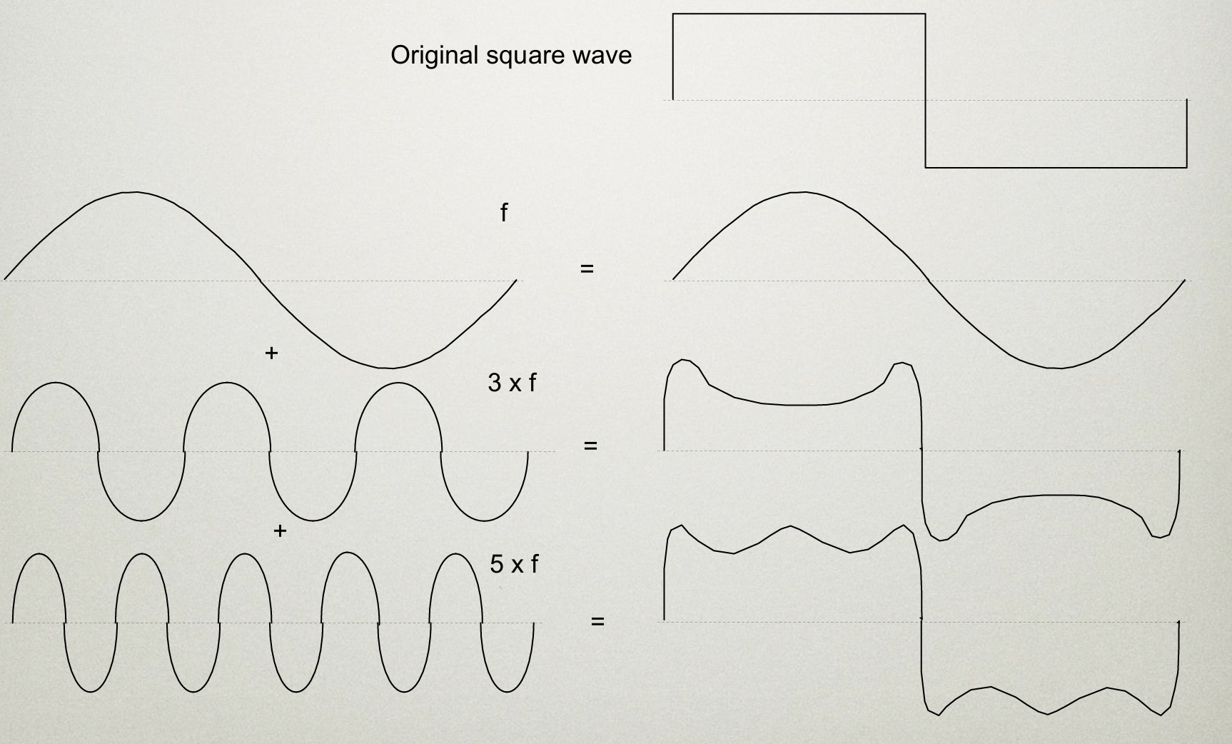
푸리에 변환을 사용하면 디지털 wave를 아날로그그 파동을 결합해서 비슷하게 만드는 법
Discrete Fourier Transform 방법
히스토그램과 같이 주파수별로 파라매터를 뽑아서 모은다.
중간값을 높이고싶으면 중간 주파수를 올리고, 낮은부분을 낮추고싶을떈 낮은 주파수를 낮추고 다시 복원하면 되니까 쉬워진다?
Segmentation
Point-dependent methods 임계값(Threshold)을 기준으로 밝기가 특정 값 이상인 픽셀을 하나의 그룹으로 분리하는 방법
Thresholding and semi-thresholding 임계갑 범위 내를 기준으로 부분을 분리하는 방법.
Adaptive thresholding 이미지의 각 부분에 맞는 임계값을 동적으로 계산하여 세그먼테이션하는 방법
Neighbourhood-dependent 픽셀의 이웃(주변) 값과 비교하여 세그먼테이션하는 방법
Edge enhancement & edge detectors 이미지에서 객체의 경계를 더 뚜렷하게 보이게 하는 방법
Boundary tracking 이미지에서 객체의 경계를 추적하는 방법입니다. 엣지 검출을 통해 찾은 경계선을 따라가면서 경계를 추적해 객체를 분리한다.
쉐이더로 구현하기 어렵다.
- Template matching 미리 정의된 템플릿(패턴)과 이미지의 부분들을 비교하여 일치하는 부분을 찾아내는 방법
예를들어, 삼각형 모양을 미리 정의해두고 Templete와 곱셈을 취해 일정값 이상이면 찾았다고 친다.
Texture Analsis (텍스쳐 분석)
엣지 검출기를 사용하여 픽셀의 그래디언트 방향을 계산하고, 이를 히스토그램으로 시각화하는 방법을 제시합니다. 이를 통해 이미지의 패턴이나 구조를 정량적으로 분석할 수 있습니다.